系统完善 高效可靠
PRODUCTS
Series
A68Y-20(W Series)
Instruction
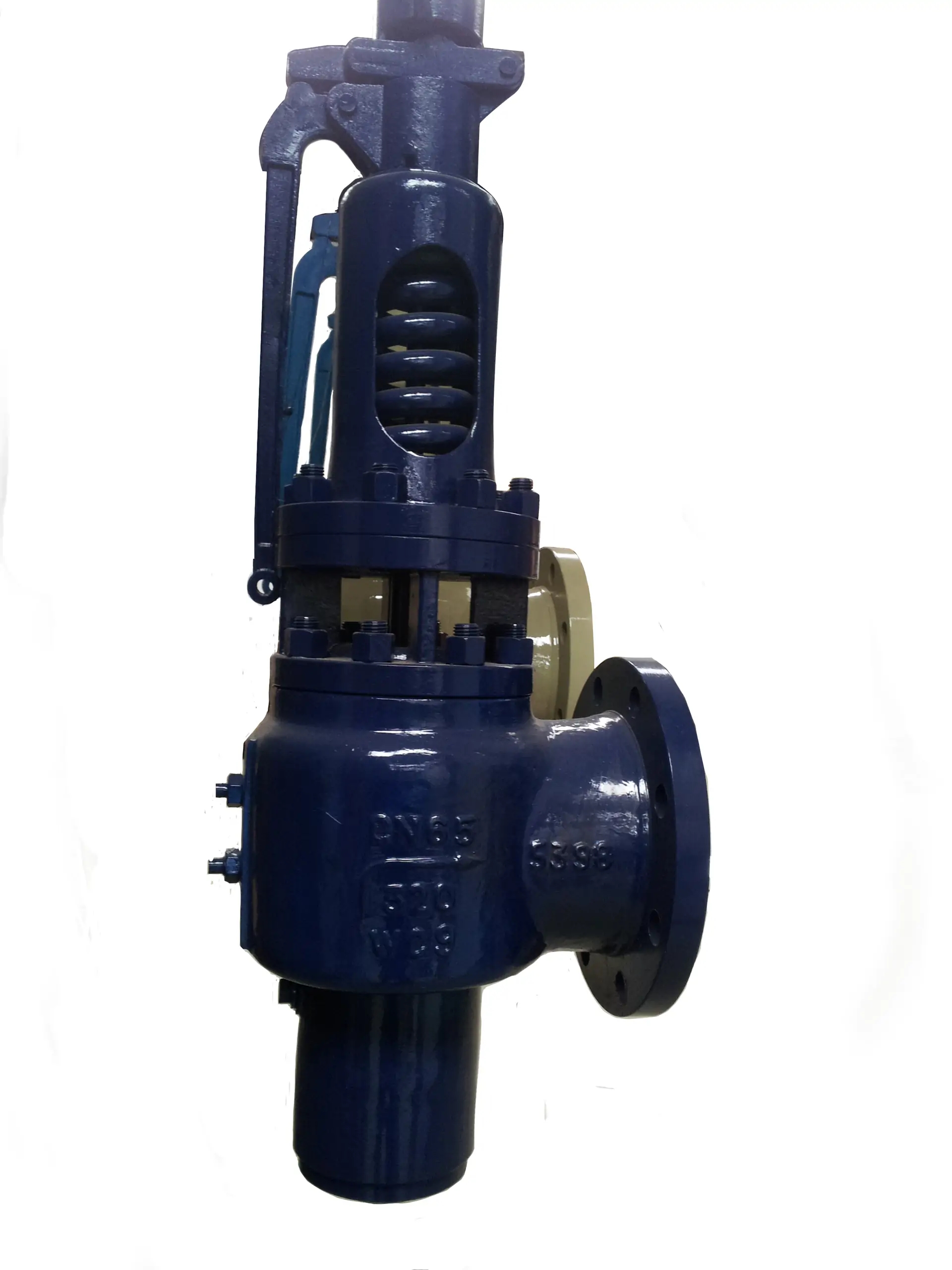
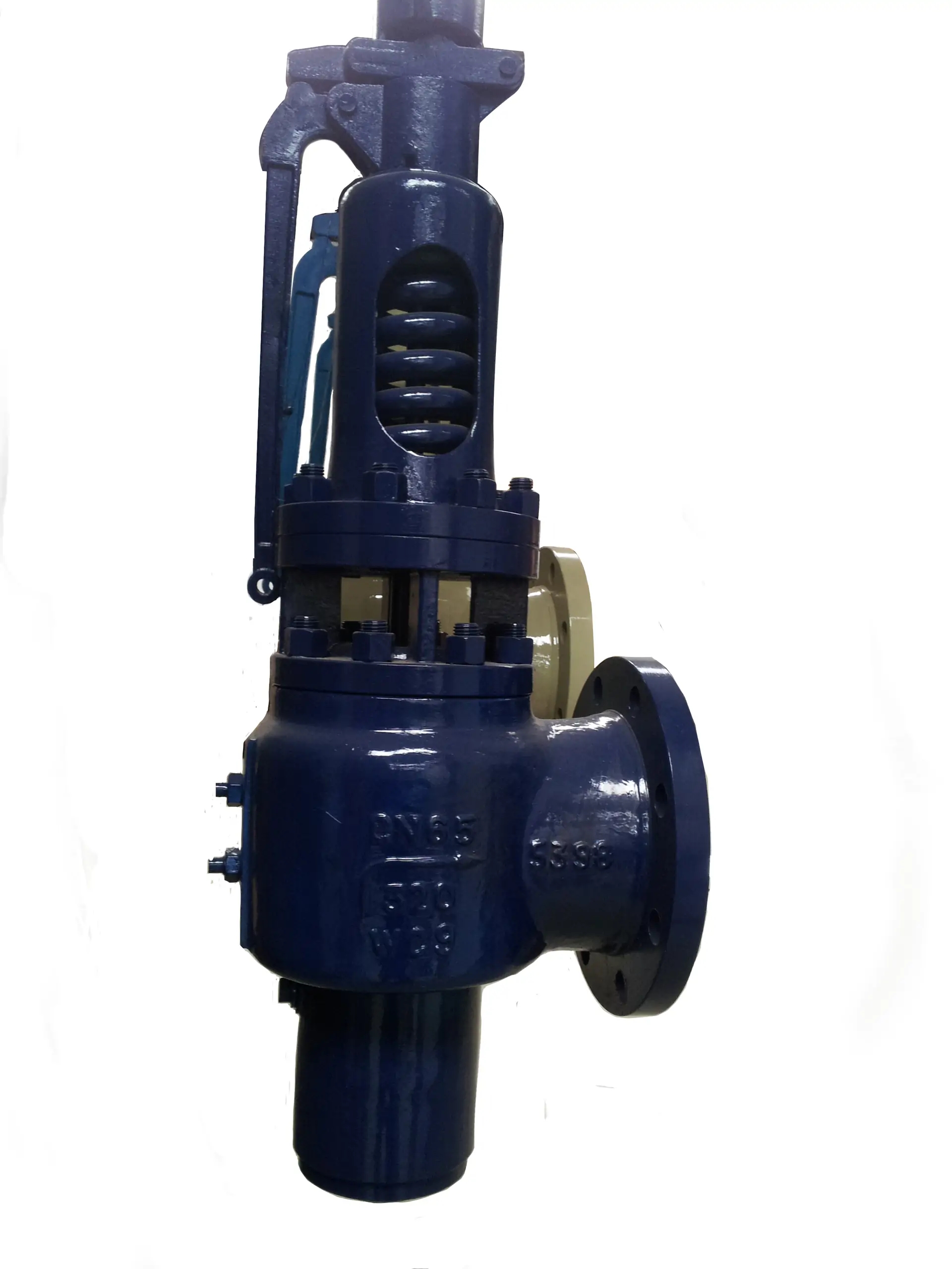
This valve is used for power plant boilers, pressure cintainers, pressure and temperature reducing device and other faciltties. It serves prevent the pressure exceeding the highest allowed pressure value and ensure the satefy of te device when working.
Structure briefing
1. The main characteristics of the spring fully bore type safety valve are: simple structure, good seal performance, accurrate opening pressure large discharge capablity, low differential reseating pressure and convenient adjustment, etc.
2.Nozzle seat: It is the loware nozzle type seat. The speed of the steam reaches the velocity of sound when passing the exit way of the seat. The sealing surface is welded by cobalt hard alloy. Large displacement coefficient, anti-friction, corrosion resistance and long durability are recognized.
3. Thermo elastic disc: the disc is thermo elastic structure. Taking the advantage of its monor out-of-shape feature when under the medium pressure, the seal ability has been raised and the problem that pre-discharge phenomenon of the main safety happens when the medium pressure approaching the set pressure has been overcome. The sealed surface of the disc has adopted the advanced technology of heat hardening to increase the hardness and the ability of anti-friction and corrsion resistance.
4. Upper Adjusting ring: the valve can acquire appropriate reseating pressure by adjusting the adjusting ring.
5. Back pressue adjusting sleeve: it is an auxiliary apparatus the serves to adjust the back pressure of the disc to acquire appropriate dif-ferential pressure for seat returning.
Installation instruction
1. The safety valve shall be installed vertically and it would be better to install the valve directly upon the adaptor of the contcuner or the pipe. The inside diameter of the adaptor shall be no less than that of the inlet pipe of the safety valve.
2. To avoid the thermal stress that is caused by the thermal expansion of the discharge pipe, the exit way of the safety valve shall be expansion with appropriate expansion joint. The inside diameter of the discharge pipe should larger that the diameter of the exit way of the valve. Its length shall be as short as possible and no bent is allowed. The weight of both the discharge pipe and the expansion joint shaal not be applied to the safety valve, and they shall be fastened upon the con-struction. The distance between both centerlines of the discharge pipe and the body shall be as short as possible.
3. The exit way of the muffler shall have enough area, in order to avoid producing back pressure that would afect the discharge capability of the valve.
4. Water drainage pipes shall be installed at the ends of both the exhaust pipe and the body; the exit of the back pressure adjusting sleeve shaal be equipped with short bend.
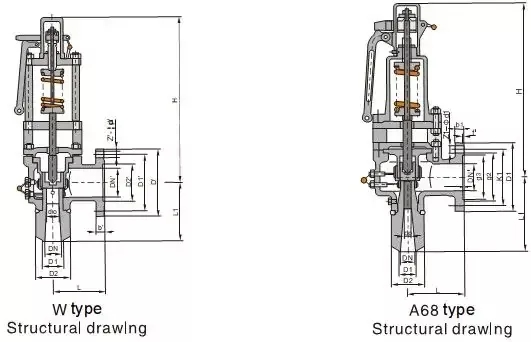
Wtype main external and connecting Dimensions(mm)
| Type | (DN) | L | L1 | D0 | H | DN' | D | D1' | D2' | B' | Z'-Φd' |
| A68Y-20 | 65 | 210 | 290 | 48 | 923 | 150 | 300 | 250 | 204 | 30 | 8-25 |
| A68Y-P5410V | 65 | 210 | 290 | 48 | 923 | 150 | 300 | 250 | 204 | 30 | 8-25 |
| A68Y-20 | 80 | 210 | 290 | 52 | 923 | 150 | 300 | 250 | 204 | 30 | 8-25 |
| A68Y-P5410V | 80 | 210 | 290 | 52 | 923 | 150 | 300 | 250 | 204 | 30 | 8-25 |
| A68Y-25 | 65 | 210 | 290 | 48 | 923 | 150 | 300 | 250 | 204 | 30 | 8-25 |
| A68Y-P5414V | 65 | 210 | 290 | 48 | 923 | 150 | 300 | 250 | 204 | 30 | 8-25 |
| A68Y-25 | 80 | 210 | 290 | 52 | 1003 | 150 | 300 | 250 | 204 | 30 | 8-25 |
| A68Y-P5414V | 80 | 210 | 290 | 52 | 1003 | 150 | 300 | 250 | 204 | 30 | 8-25 |
| A68Y-32 | 65 | 210 | 290 | 48 | 1083 | 150 | 300 | 250 | 204 | 30 | 8-25 |
| A68Y-P5420V | 65 | 210 | 290 | 48 | 1083 | 150 | 300 | 250 | 204 | 30 | 8-25 |
| A68Y-32 | 80 | 210 | 290 | 52 | 1083 | 150 | 300 | 250 | 204 | 30 | 8-25 |
| A68Y-P5420V | 80 | 210 | 290 | 52 | 1083 | 150 | 300 | 250 | 204 | 30 | 8-25 |
| A68Y-10 | 150 | 310 | 525 | 100 | 1158 | 300 | 485 | 430 | 390 | 36 | 16-30 |
| A68Y-P543.82V | 150 | 310 | 525 | 100 | 1158 | 300 | 485 | 430 | 390 | 36 | 16-30 |
| A68Y-10 | 200 | 310 | 525 | 125 | 1158 | 300 | 485 | 430 | 390 | 36 | 16-30 |
| A68Y-P542.5V | 200 | 310 | 525 | 125 | 1158 | 300 | 485 | 430 | 390 | 36 | 16-30 |
A68 type main external and connecting dimension(mm)
| Type | (DN) | L | L1 | D0 | DN' | D | D1' | D2' | B' | Z'-Φd' | |
| A68E210/550V1 | 65 | 240 | 280 | 46 | 100 | 265 | 210 | 150 | 38 | 8-30 | |
| A68SB160/400C1 | 65 | 260 | 280 | 52 | 150 | 320 | 250 | 204 | 30 | 8-25 | |
| A68E210/400C1 | 80 | 190 | 305 | 58 | 150 | 340 | 280 | 204 | 38 | 8-34 | |
| A68E210/550V1 | 80 | 190 | 305 | 58 | 150 | 340 | 280 | 204 | 38 | 8-34 | |
| A68E210/550V2 | 80 | 190 | 305 | 60 | 150 | 300 | 250 | 204 | 30 | 8-25 | |
| A68E160/550V1 | 100 | 320 | 340 | 70 | 250 | 445 | 385 | 313 | 42 | 12-34 | |
| A68SB100V1 | 100 | 260 | 325 | 80 | 150 | 300 | 250 | 204 | 30 | 8-25 | |
| A68SB100V2 | 100 | 260 | 325 | 85 | 150 | 300 | 250 | 204 | 30 | 8-25 | |
| A68SB100C1 | 150 | 305 | 385 | 115 | 250 | 445 | 385 | 313 | 42 | 12-34 | |
| A68SB100C2 | 150 | 305 | 385 | 110 | 250 | 445 | 385 | 313 | 42 | 12-34 | |
| A68SB100C3 | 150 | 305 | 385 | 120 | 250 | 445 | 385 | 313 | 42 | 12-34 | |
| A68SB100V1 | 150 | 305 | 385 | 115 | 250 | 445 | 385 | 313 | 42 | 12-34 | |
| A68SB100V2 | 150 | 305 | 385 | 100 | 250 | 445 | 385 | 313 | 42 | 12-34 | |
| A68SC2500C2 | 1 1/2"(40) | 155 | 165 | 18 | Outlet 3" x 300Lb | ||||||
| A68SC1500I1 | 2"(50) | 216 | 280 | 33 | Outlet 3" x 300Lb | ||||||
| A68C1500C1 | 2 1/2"(65) | 216 | 280 | 40 | Outlet 3" x 300Lb | ||||||
| A68C1500C2 | 2 1/2"(65) | 216 | 305 | 46 | Outlet 3" x 300Lb | ||||||
The dimensions of D1, D2 can manufacture upon client's requirement.
BW ends for HP and Superheated Steam


